Today many different programs for calculating the loudspeaker box of your favorite type are available either as free ware, share ware or for a reasonable amount of money. They range from DOS based programs with simple user interface to advanced Windows programs with built-in driver database and almost all of these programs utilize the results of the work made and published by A. N. Thiele and R. H. Small some thirty years ago. As was common these days the full driver-box model was reduced and simplified to ease calculation and to derive nomographs so that correct alignment could be obtained just with ruler and pencil.
However today these simplifications are no longer necessary and the full driver-box model can be implemented either as a program or as a spread sheet, which is the case with UniBox. The full driver-box model as implemented here includes individual control of absorption, leakage and port losses and the effect of each can easily be observed. Furthermore, new graphs commonly not shown includes the sound pressure level produced by the leaks, speaker impedance and step response. UniBox covers the following box types.
| Simulation with UniBox | |
| Closed Box | |
| Vented Box | |
| Passive Radiator Box | |
| Bandpass Single Tuned Box | |
To utilize the program you need the following Thiele-Small Parameters (TSP) for the wanted drive unit.
| Drive Unit Parameters | |
| Fs | Driver free air resonance frequency |
| Re | Driver voice coil DC resistance |
| Qms | Q of driver at Fs considering mechanical losses only |
| Qes | Q of driver at Fs considering electrical losses only |
| Sd | Effective area of driver diaphragm |
| Vas | Volume of air having same acoustic compliance as the driver |
| Xmax | Peak linear driver excursion |
| Le | Equivalent voice coil inductance |
| Le2 | Improved model of voice coil inductance simulating Eddy currents |
| Re2 | Improved model of voice coil inductance simulating Eddy currents |
| Pn | Nominal power handling of driver |
UniBox will simulate the effect of series resistance due to cabling and amplifier output impedance as well as a passive low pass crossover network of up to 4. order. To specify external components enter the corresponding values or set the values equal to zero to remove them from the circuit.
| External Components | |
| Rs | Series resistance due to amplifier output impedance and speaker cabling |
| Lco1 | 1. crossover inductance |
| Rco1 | Series resistance of 1. crossover inductance |
| Cco1 | 1. crossover capacitance |
| Lco2 | 2. crossover inductance |
| Rco2 | Series resistance of 2. crossover inductance |
| Cco2 | 2. crossover capacitance |
Enter the name and model of the drive unit, its TSP values and any external components as shown below.

Additional drive unit parameters are automatically calculated and a box type suggested based on the given parameters.
It is possible to change the speed of sound, density of air and a linear cone overdrive coefficient, which allows the user to specify the amount of overdrive relative to Xmax acceptable when considering harmonic distortion.
During the optimization process you may end up with many constants changed especially when changing Q-values for absorption, leakage and the port. To get back to the initial values click
| Set All Constants to Default Values |
You can save up to 2000 designs in the Design Data Base. The driver TS parameters and your box alignment data for closed, vented, passive radiator including the TS parameters for the passive radiator itself and bandpass single tuned boxes are all saved using the text in the driver name field as the data base record name. To save your design click
| Save |
To open an existing design choose it from the drop down list using the scroll facility.
If you want to delete an existing data base entry first open it and then click
| Delete |
You can export your total Design Data Base or import and append a Design Data Base. In this way you can share TS parameters and box designs with your DIY friends. Click
| Import | Export |
To ease driver selection you can sort your Design Data Base by Name, Fs, Qes and Sd. Click
| Name | Fs | Qes | Sd |
From the drive unit configuration drop down selection box you can select between 10 different configurations.
| Drive Unit Configuration | |
| Single drive unit | The simplest case with only one drive unit. |
| 2 drive in series | 2 equal drive units electrically connected in series. |
| 2 drive units in parallel | 2 equal drive units electrically connected in parallel. |
| 3 drive in series | 3 equal drive units electrically connected in series. |
| 3 drive units in parallel | 3 equal drive units electrically connected in parallel. |
| 4 drive in series | 4 equal drive units electrically connected in series. |
| 4 drive units in parallel | 4 equal drive units electrically connected in parallel. |
| 4 drive units, series of 2 X 2 in parallel | 4 equal drive units electrically connected as a series connection of 2 X 2 units in parallel. |
| 2 drive in series, compound | 2 equal drive units electrically connected in series and mounted behind each other with a small coupling volume. Also known as Isobaric. |
| 2 drive units in parallel, compound | 2 equal drive units electrically connected in parallel and mounted behind each other with a small coupling volume. Also known as Isobaric. |
You can export the frequency response data as a FRD file and the impedance data as a ZDA file for use in other programs like the FRC developed by Paul Verdone. Visit his site for links to a whole suite of related speaker design programs.
To export the wanted file for closed, vented, passive radiator or bandpass single tuned alignment click the corresponding
| FRD |
| ZDA |
The calculation routines of the Standard Design are based on a simplified model which is equivalent to that used by most other box calculation programs. For the Standard Design only the wanted total closed box Q (Qtc) can be entered and the program will calculate Vb, Fb, F3, the response peak and the maximum allowable power dissipated in the drive unit if Xmax is not to be exceeded. Note that this calculation only takes a single combined leakage loss parameter into account which usually is referred to as Ql. UniBox uses a Ql value of approximately 8.
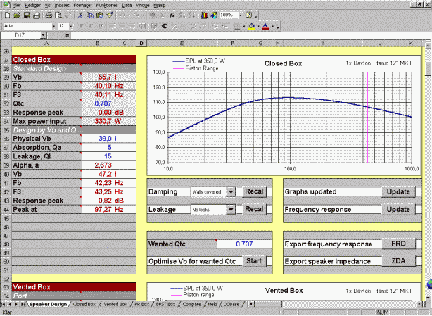
The full box model takes both absorption and leakage into account. To calculate the closed box frequency response enter your choice of box physical volume (Vb), Q due to box absorption (Qa) and Q due to box and driver leakage (Ql). The program will calculate alpha, Vb, Fb, F3 and the response peak and the frequency at which it occurs. You can change the parameters and see the result in the frequency response graph.
To activate fast calculation of the frequency response or to calculate all graphs click the relevant button
| Update |
Given the Qa and Ql values you can based on a wanted total closed box Q (Qtc) calculate the required box volume by pressing
| Optimise Vb for wanted Qtc |
When you want to investigate the full model closed box design more carefully click the Closed Box sheet selection tab. It will show the frequency response including additional graphs and the cone excursion at the selected power level. Remember to update all graphs before viewing.
Start by entering the number of ports, the port diameter and the port area is automatically calculated. The port end-correction depends on the port mounting (flush mounted or not) and the shape (flared or non-flared). You can enter your own value or select one of the pre-calculated values by clicking the port type drop down selection box.
The port parameters are valid for both the standard design and the full model.
The calculation routines of the Standard Design are based on a simplified model which is equivalent to that used by most other box calculation programs. For the Standard Design the following parameters are immediately calculated. Vb, Fb, F3, approximate minimum port diameter and port length. Note again that this calculation does not take any box damping material into account so Vb is the effective box volume seen by the driver. The approximate minimum port diameter is calculated as a suggested value to avoid excessive turbulence noise in the port at high sound levels. The port length is calculated according to the specified port diameter and box tuning frequency Fb.

The full box model takes all losses into account resulting from absorption, leakage and the port. To calculate the vented box frequency response enter your choice of box physical volume (Vb), Q due to box absorption (Qa), Q due to box and driver leakage (Ql) and Q due to the port (Qp). Choose a box tuning frequency Fb and the program will calculate alpha, Vb, F3, the response peak and the frequency at which it occurs as well as the port length according to the specified port diameter and Fb. Also the approximate minimum port diameter is calculated as a suggested value to avoid excessive turbulence noise in the port at high sound levels, but it should always be checked with the actual port air speed graph.
Furthermore, the port first self resonance frequency is approximated, which can be used as guidance to see whether it falls within the wanted woofer frequency band. If you want to include the effect of the port self resonance in all the graphs check the check-box.
After changing the parameters update the graphs by clicking the relevant button
| Update |
Given the Vb, Qa, Ql and Qp values you can based on a wanted response peak calculate the required box tuning frequency Fb by pressing
| Optimise Fb for wanted peak |
When you want to investigate the full model vented box design more carefully click the Vented Box sheet selection tab. It will show the frequency response including additional graphs and the cone excursion as well as the port air speed at the selected power level. Remember to update all graphs before viewing.
A branch of modern woofers of to day have rather heavy diaphragms, low mechanical compliance figures, low resonance frequencies and powerful motors for reasonably sensitivity. These drive units are designed for sub woofers capable of delivering high sound pressure levels at low frequencies in small cabinets. If a vented box design is attempted, the port length necessary to tune the system will be very long and impractical. In this case a passive radiator design may be the solution, as the large and heavy diaphragm of the radiator will eliminate the port noise and self resonance problems of the vented design.
A passive radiator design will have a steeper roll off and a notch at low frequencies. However, it may be just the right design for the purpose. Good designs utilizing passive radiators are made by Sunfire and Velodyne.
As input for the calculations you need the following Thiele-Small Parameters (TSP) for the wanted passive radiator.
| Passive Radiator Parameters | |
| Fsp | PR free air resonance frequency |
| Mmp | Mechanical mass of PR diaphragm |
| Qms | Q of driver at Fsp considering mechanical losses only |
| Sdp | Effective area of PR diaphragm |
| Xpmax | Peak linear PR excursion |
Enter the name and model of the passive radiator and its TSP values as shown below.

Enter the number of passive radiators included in the design and the additional parameters of the passive radiator(s) are automatically calculated which can be used for a cross check, if they are given by the manufacturer or you have measured them yourself. If is important to know both driver and passive radiator TS parameters with good precision to obtain the wanted alignment.
The full box model takes all losses into account resulting from absorption, leakage and the passive radiator mechanical loss. To calculate the passive radiator box frequency response enter your choice of box physical volume (Vb), Q due to box absorption (Qa), Q due to box, driver and passive radiator leakage (Ql). The passive radiator mechanical loss (Qmp) has already been entered. The program will calculate Vb, Fb, F3, the response peak and the frequency at which it occurs as well as the system parameters a, u and h.
After changing the parameters update the graphs by clicking the relevant button
| Update |
Some passive radiator offers the possibility to add mass to the diaphragm by mounting weights, and by doing so the resonance frequency is lowered. It is therefore possible to tune the system to the wanted response by adding or subtracting mass and changing box volume. However, not all drive units are suitable for a passive radiator box design and you will soon find out.
Given the values Qa and Ql you can by adjusting passive radiator mass and box volume optimise the frequency response. Press the buttons:
| Down | Up |
When you want to investigate the full model passive radiator box design more carefully click the PR Box sheet selection tab. It will show the frequency response including additional graphs and the cone excursion graphs for both the drive unit and the passive radiator at the selected power level. Remember to update all graphs before viewing.
Start by entering the number of ports, the port diameter and the port area is automatically calculated. The port end-correction depends on the port mounting (flush mounted or not) and the shape (flared or non-flared). You can enter your own value or select one of the pre calculated values by clicking the port type drop down selection box.

The full box model takes all losses into account resulting from absorption, leakage and the port. To calculate the bandpass single tuned box frequency response enter your choice of the parameters below and click Update.
| Bandpass Single Tuned Alignment Parameters | |
| Vb1 | Physical volume of closed box part |
| Qa1 | Q due to absorption losses of closed box part |
| Ql1 | Q due to leakage losses of closed box part |
| Vb2 | Physical volume of vented box part |
| Qa2 | Q due to absorption losses of vented box part |
| Ql2 | Q due to leakage losses of vented box part |
| Fb2 | Tuning frequency of vented box part |
| Ql12 | Q due to mutual leakage losses between closed and vented box parts |
| Qp | Q due to friction losses of port |
The port self resonance can be rather disturbing for bandpass boxes especially when the port length dictates a low self resonance frequency. To see the approximate effect of the port self resonance in all graphs click the check box.
As the calculations are quite lengthy the graphs are not updated automatically every time a parameter is changed. To calculate all graphs click
| Update |
To ease the selection of and provide a reasonable guess on Qa1, Ql1, Qa2, Ql2, Ql12 and Qp a drop down selection box and a recal function are provided for each parameter. It is impossible to give accurate values as they depend on the actual damping material used and how hard it is stuffed, where it is placed and upon the unavoidable leaks in the cabinet and driver. Also the actual port shape and dimensions will influence Qp.
For bandpass tuned speakers there exist many alignments which gives a flat bandpass characteristic but with changing bandwidth and efficiency. UniBox provides two automatically calculated alignments but you can easily produce others by manual entry of parameters.
Given the Qa1, Ql1, Qa2, Ql2, Ql12 and Qp you can activate calculation of the two alignments by clicking
| Optimise for efficiency | Start |
| Optimise for low frequency | Start |
When you want to investigate the full model bandpass single tuned box design more carefully click the BPST Box sheet selection tab. It will show the frequency response including additional graphs and the cone excursion as well as the port air speed at the selected power level. Remember to update all graphs before viewing.
If you want to compare the frequency response, cone excursion and step response of the closed, vented, passive radiator and bandpass single tuned box alignments click the Compare sheet selection tab. It will show the graphs for easy comparison.
The step response for the closed, vented, passive radiator or bandpass single tuned box alignments is calculated whenever the
| Calculate Step Response |
Go to the download page to get the program.
If you have any suggestions for improvements and additions your e-mails are welcome.
![]() You have been listening to some funky jazz.
You have been listening to some funky jazz.